Hedgehog Network Fabric
The Hedgehog Open Network Fabric is an open-source network architecture that provides connectivity between virtual and
physical workloads and provides a way to achieve network isolation between different groups of workloads using standard
BGP EVPN and VXLAN technology. The fabric provides a standard Kubernetes interface to manage the elements in the
physical network and provides a mechanism to configure virtual networks and define attachments to these virtual networks.
The Hedgehog Fabric provides isolation between different groups of workloads by placing them in different virtual
networks called VPC's. To achieve this, it defines different abstractions starting from the physical network where
a set of Connection objects defines how a physical server on the network connects to a physical switch on the fabric.
Underlay Network
The Hedgehog Fabric currently supports two underlay network topologies.
Collapsed Core
A collapsed core topology is just a pair of switches connected in a MCLAG configuration with no other network elements. All workloads attach to these two switches.

The leaves in this setup are configured to be in a MCLAG pair and servers can either be connected to both switches as a MCLAG port channel or as orphan ports connected to only one switch. Both the leaves peer to external networks using BGP and act as gateway for workloads attached to them. The configuration of the underlay in the collapsed core is very simple and is ideal for very small deployments.
Spine-Leaf
A spine-leaf topology is a standard Clos network with workloads attaching to leaf switches and the spines providing connectivity between different leaves.
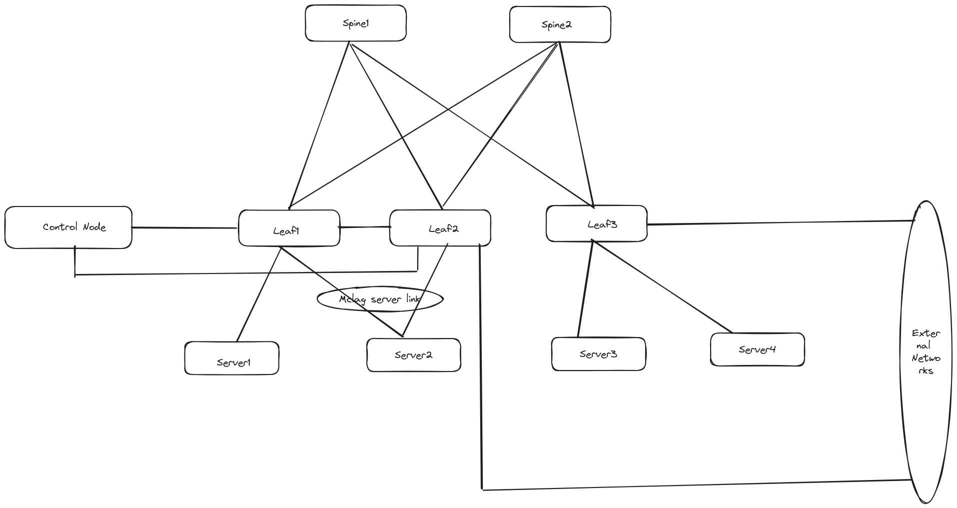
This kind of topology is useful for bigger deployments and provides all the advantages of a typical Clos network. The underlay network is established using eBGP where each leaf has a separate ASN and peers will all spines in the network. RFC7938 was used as the reference for establishing the underlay network.
Overlay Network
The overlay network runs on top the underlay network to create a virtual network. The overlay network isolates control and data plane traffic between different virtual networks and the underlay network. Virtualization is achieved in the Hedgehog Fabric by encapsulating workload traffic over VXLAN tunnels that are source and terminated on the leaf switches in the network. The fabric uses BGP-EVPN/VXLAN to enable the creation and management of virtual networks on top of the physical one. The fabric supports multiple virtual networks over the same underlay network to support multi-tenancy. Each virtual network in the Hedgehog Fabric is identified by a VPC. The following subsections contain a high-level overview of how VPCs are implemented in the Hedgehog Fabric and its associated objects.
VPC
The previous subsections have described what a VPC is, and how to attach workloads to a specific VPC. The following bullet points describe how VPCs are actually implemented in the network to ensure a private view the network.
- Each VPC is modeled as a VRF on each switch where there are VPC attachments defined for this VPC. The VRF is allocated its own VNI. The VRF is local to each switch and the VNI is global for the entire fabric. By mapping the VRF to a VNI and configuring an EVPN instance in each VRF, a shared L3VNI is established across the entire fabric. All VRFs participating in this VNI can freely communicate with each other without the need for a policy. A VLAN is allocated for each VRF which functions as an IRB VLAN for the VRF.
- The VRF created on each switch corresponding to a VPC configures a BGP instance with EVPN to advertise its locally attached subnets and import routes from its peered VPCs. The BGP instance in the tenant VRFs does not establish neighbor relationships and is purely used to advertise locally attached routes into the VPC (all VRFs with the same L3VNI) across leaves in the network.
- A VPC can have multuple subnets. Each subnet in the VPC is modeled as a VLAN on the switch. The VLAN is only locally significant and a given subnet might have different VLANs on different leaves on the network. A globally significant VNI is assigned to each subnet. This VNI is used to extend the subnet across different leaves in the network and provides a view of single stretched L2 domain if the applications need it.
- The Hedgehog Fabric has a built-in DHCP server which will automatically assign IP addresses to each workload depending on the VPC it belongs to. This is achieved by configuring a DHCP relay on each of the server facing VLANs. The DHCP server is accessible through the underlay network and is shared by all VPCs in the fabric. The inbuilt DHCP server is capable of identifying the source VPC of the request and assigning IP addresses from a pool allocated to the VPC at creation.
- A VPC by default cannot communicate to anyone outside the VPC and specific peering rules are required to allow communication to external networks or to other VPCs.
VPC Peering
To enable communication between 2 different VPCs, one needs to configure a VPC peering policy. The Hedgehog Fabric supports two different peering modes.
- Local Peering: A local peering directly imports routers from the other VPC locally. This is achieved by a simple import route from the peer VPC. In case there are no locally attached workloads to the peer VPC the fabric automatically creates a stub VPC for peering and imports routes from it. This allows VPCs to peer with each other without the need for a dedicated peering leaf. If a local peering is done for a pair of VPCs which have locally attached workloads, the fabric automatically allocates a pair of ports on the switch to route traffic between these VRFs using static routes. This is required because of limitations in the underlying platform. The net result of these limitations is that the bandwidth between these 2 VPCs is limited by the bandwidth of the loopback interfaces allocated on the switch. Traffic between the peered VPCs will not leave the switch that connects them.
- Remote Peering: Remote peering is implemented using a dedicated peering switch/switches which is used as a rendezvous point for the 2 VPC's in the fabric. The set of switches to be used for peering is determined by configuration in the peering policy. When a remote peering policy is applied for a pair of VPCs, the VRFs corresponding to these VPCs on the peering switch advertise default routes into their specific VRFs identified by the L3VNI. All traffic that does not belong to the VPCs is forwarded to the peering switch which has routes to the other VPCs and gets forwarded from there. The bandwidth limitation that exists in the local peering solution is solved here as the bandwidth between the two VPCs is determined by the fabric cross section bandwidth.
Created: December 22, 2023